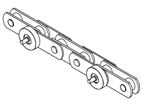
 Fig. 1: Step Chain. Photo: © Löher
For this reason, the concept of "Heavy Duty" escalator has emerged. The Turkish company Meteor Löher designed and prototyped such a "Heavy Duty Type".
By Cemil Cagar
Heavy Duty escalators are expected to reach higher travel distances with a higher passenger load than standard escalators, be exposed to busy working hours, and require less service. For this reason, the design and manufacturing processes of Heavy Duty escalators should be different from standard escalators.
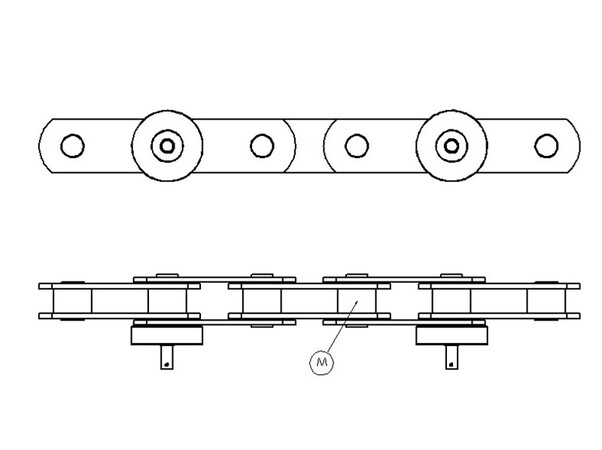 Fig. 2: Chain Detail Photo: © Löher
The followings were determined as the main design criteria:
• Chain selection that can withstand maximum passenger load and meet lifespan
• Lower and upper turning radius to ensure passenger comfort and meet load distribution
• System design to support the resulting loads, high travel distance and long life
• Handrail drive system design that can operate at higher travel distances without slipping
Based on these criteria, it was decided to build a prototype heavy duty escalator to see the results of the study. In the prototype design, 2.500 mm cruising height, 30° climbing angle and 800 mm step width were preferred.
1. Chain Selection
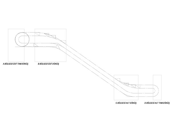 Fig. 3: Chain Cruise Line. Photo: © Löher
The step chain, which should normally be selected according to the cruising height and passenger load, was kept high for the prototype design discussed in this study and a Ketten Wulf chain with a capacity of 540 kN was chosen. A wheel with a diameter of 100 mm was selected. In the selected chain, the wheels are located on the inside of the chain (See Figure 1 and Figure 2).
In order to be able to transmit more load and have a longer life, the drive in this chain is provided by the shafts (M Shaft) connecting the chain links, not by the wheels attached to the chain (See Figure2). In this way, more load can be transmitted with a longer life.
Throughout the system, in all turning areas where the load would be high due to chain tensioning (See Figure 3, A-B-C-D regions), all loads were transferred through these shafts, and no load was placed on the plastic-equipped chain wheels. The fact that the load transmission shafts, and chain wheels are on different axes in the selected chain caused the change of all rail systems in the chain travel line and the gear design that will drive the chain throughout the system.
2. Main Drive Gear and System Design
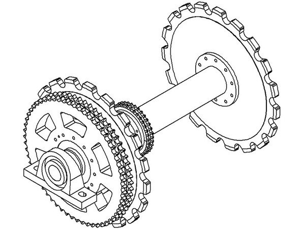 Fig. 4: Main Drive System. Photo: © Löher
This change in the chain caused the size of the sprocket to drive the chain to be increased. To meet the changing chain and load needs, the rolling diameter has been enlarged and gears have been designed to drive the chain from the central shafts. Instead of the sleeve shaft gear used in our standard escalators, a shaft made of St 52 (S355JR) steel bar was used to meet the increased load and life requirement (See Figure 4).
Depending on the changed drive system, the bearing system was changed and rolling bearing materials were used. Mounting consoles are designed to mount these bearing materials to the main construction, as well as to perform adjustments and similar operations when necessary.
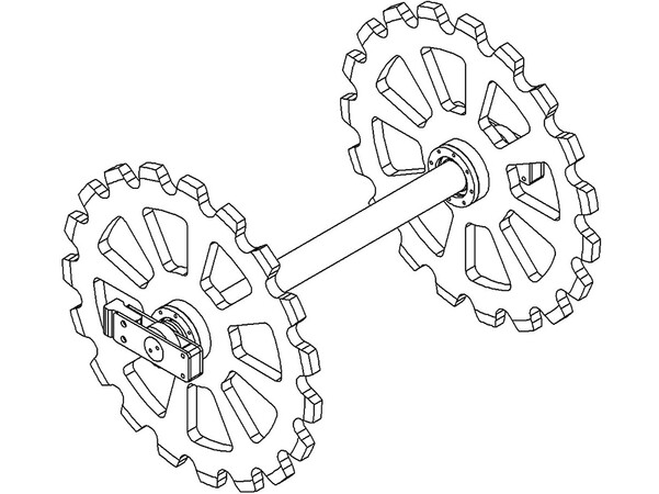 Fig. 5: Hand rail rotation gear system. Photo: © Löher
For sound insulation, plastic-based sound absorbing materials are mounted at the contact points of the chain shafts with the gear surface. To drive the main drive system with the motor, a double row gear is designed and mounted on the same axis as the main drive gear.
The gear selected to provide the handrail drive is mounted on the main shaft. While selecting the sprocket to be used in the handrail drive, care was taken to ensure that the handrail travel speed was compatible with the passenger travel speed, and the number of sprocket teeth was calculated accordingly.
3.Station Design
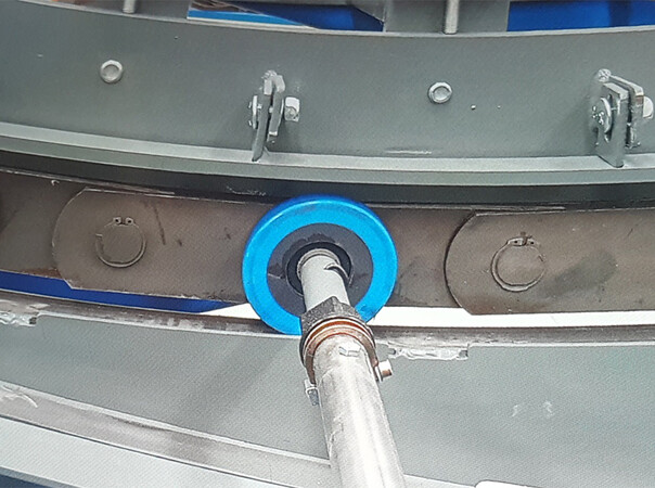 Fig. 6: Chain Support Lower Stations. Photo: © Löher
In order to support the increasing amount of load and the force that will drive the chain, the full rotation of the step chain at the lower station (Figure 3, Region D) is provided by the gear supported by the rolling bearing. In this way, load transfer and movement are facilitated.
To support the increased load and increase passenger comfort, step travel radius at the lower and upper stations have been increased (See Figure 3, B and C region). Stations have been redesigned according to changing dimensions. Plastic-based, friction-facilitating materials have been used in the chain turns to provide sound insulation, reduce wear and prevent metal-metal friction.
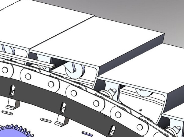 Fig. 7: Chain Support Upper Stations. Photo: © Löher
In order to protect these materials from abrasion and similar situations that may occur during escalator work, these materials are mounted with adjustable consoles (See Figure 6 and Figure 7).
Thus, lower friction force was achieved, and load loss was reduced in the return lines where the load was high (Figure 3, B and C regions). Additionally, sound is reduced because metal-metal friction is prevented.
4. Construction Design
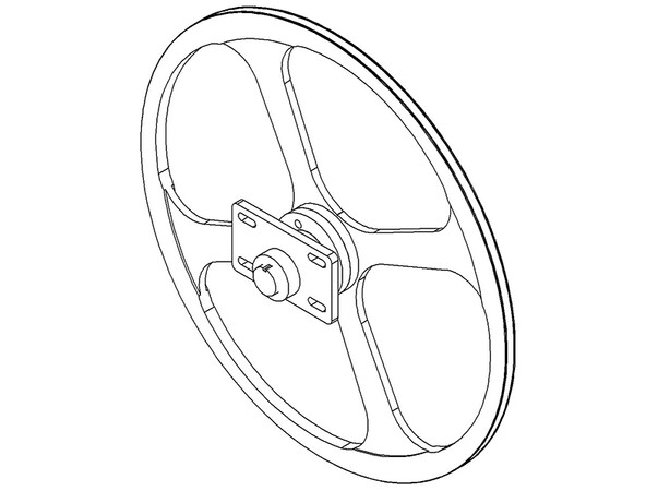 Fig. 8: Hand Rail Return/Drive Pulley. Photo: © Löher
In the selected chain, the fact that the load transmission shafts, and chain wheels are on different axes made it necessary for the right and left chain line to be positioned outside the steps. This necessity caused the system to be wider than standard escalators. In addition, the changing main drive system and bearing design also affected the width increase.
These reasons have caused the "Heavy Duty" escalator to be wider than the standard escalator. Due to reasons such as changing stations, the construction design was changed, and a construction design was made to support the new system.
5. Handrail Drive System Design
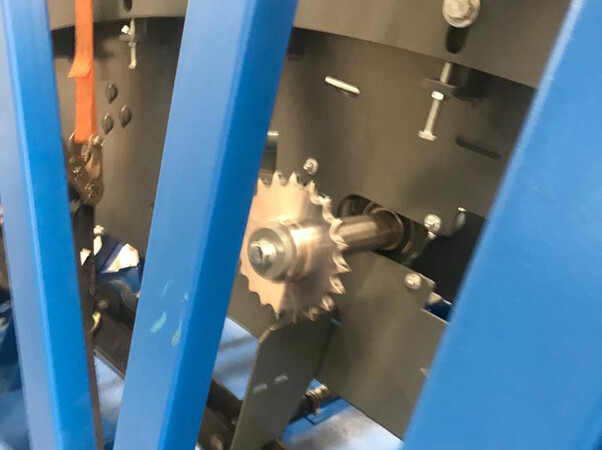 Fig. 9: Hand Rail Drive Gears. Photo: © Löher
Channel type handrails, which have a longer lifespan, are preferred in "Heavy Duty" escalators. In the lower and upper full rotations, the movement of the handrail is provided by the handrail pulleys supported by rolling bearings (See Figure 8).
Handrail drive is provided by driving the gears in the centers of the handrail pulleys in the upper area. The movement in question is provided by the chains between these gears and the handrail drive gears at the upper station. Chain tension is provided by the consoles to which these sprockets are connected (See Figure 9).
6. Results
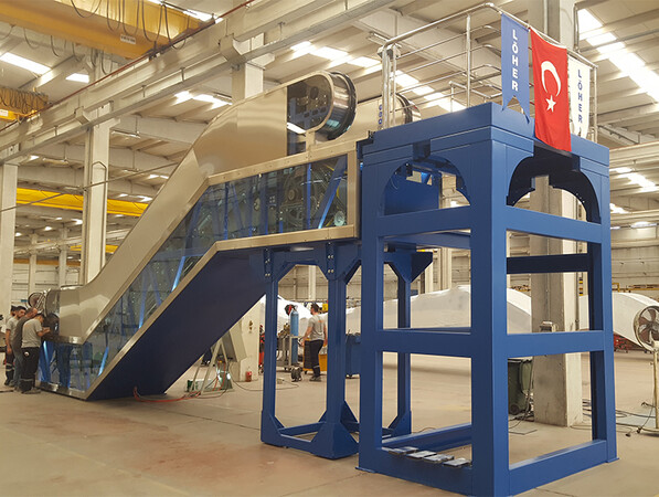 Photo: © Löher
Using the design steps mentioned in the article, a short version of the "Heavy Duty" escalator, a prototype escalator with a travel height of 2500 mm, was designed, and the manufacturing and testing of this prototype was successfully carried out in our factory.
In the light of this information, it is possible to design and produce escalators that reach higher travel distances.
The author is Mechanical Engineer and Head of the Engineering Department at the Meteor Group Escalator Factory.
More information: loher.com.tr
loher.com.tr/en


Write a comment