Digital “safety circuit”: fast installation, simple diagnosis
Intec will be unveiling its new DSS safety system at the interlift: this involves all safety-relevant signals and sensors being electronically recorded and analysed.
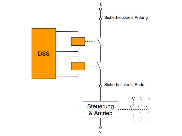
Hence, the "safety circuit" now only consists of the power supply (including fuse protection) and the DSS master with a relay output (see Figure 1).
The DSS safety system was developed according to the EN 61508 standard series, which takes up PESSRAL (see box) to guarantee a safe product with an SIL3 (safety integrity level).
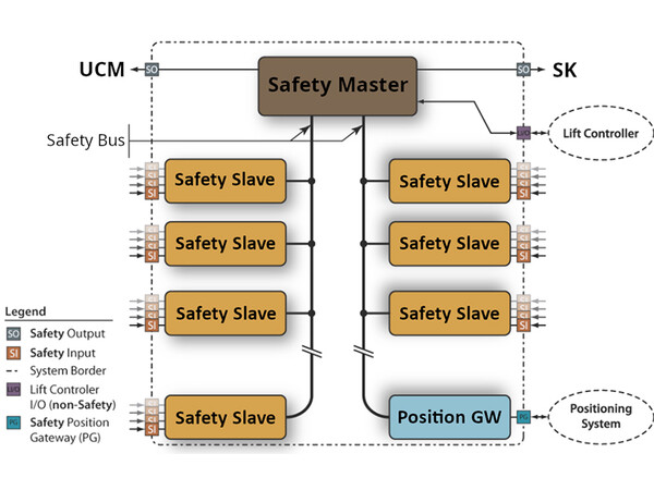
The DSS safety system consists of the safety master and up to 62 safety slaves, which are connected via two safety bus systems with the master. A safety bus connects to the car via the lift cable, the other bus runs through the shaft. Moreover, a safety-based position measurement system is connected to the safety bus via a position gateway, which provides the position information needed (see Figure 2).
Safety slaves: direct connection
 Figure 1. Photo: © Intec
All safety switches of a lift are connected directly to the inputs of the safety slaves. Conventional safety switches can be used here but using unsafe sensors is possible too. This can be a great advantage for example in a very dirty environment. Instead of conventional landing door contacts, which are very subject to failure especially in such environments, wear-free inductive sensors can be used.
All information regarding the safety slaves and of the position gateway undergo software-based processing in the safety master. Depending on the particular operating state of the lift, the relay output on the safety master is then either switched on or off and as a result the travel of the lift facilitated or prevented.
As a result, the DSS system offers completely new options. Primarily, all relevant requirements from EN 81-20 and EN 81-21 are of course realised.
These include:
• detection of uncontrolled movements
• overspeed shutdown
• deceleration control
• door zone bypassing
• electrical shelter protection
Position switches can be dispensed with completely. Additional contacts or similar installations on the landing door for shaft access control are dispensed with since every landing door is monitored individually.
The DSS safety system has a CANopen lift interface according to CiA 417 via which information can be exchanged with the lift controller.
Simple troubleshooting
 Figure 2. Photo: © Intec
New approaches arise for diagnosis and troubleshooting with the DSS system. Every safety contact is analysed individually and thus in the event of faults it is very easy to find the corresponding fault source.
As a result of the separate monitoring of every safety contact, dirt or contact deteriorations are detected by the DSS system and are already reported before the failure of the lift.
Moreover, the DSS safety system offers a great increase in safety. For example, when bypassing the door contacts, only the landing door contacts on the floor affected are bypassed for which there is a trip request. According to the current state of technology, all landing door contacts are always bypassed in conventional systems due to the series connection.
Deactivate signal transmitter
Defective signal transmitters or the corresponding inputs of the safety slaves can be deactivated in a targeted manner in the DSS system for the replacement of defective safety switches or sensors. As soon as a safety input is deactivated, travel of the lift is only possible with the recall or inspection controller.
Forgetting a "wire jumper" for these purposes as in conventional lifts is no longer possible here. EN 81-20 admittedly already makes provision for a permanently installed bypass option for defective safety switches but this only refers to door contacts and then for example bypasses all landing door contacts on one access side simultaneously.
There is a special test mode for start-up as well as for recurrent inspection, which guarantees that really every safety contact is actuated for the test. As long as this is not the case, the DSS system remains in test mode and normal trips are not possible. Installation of the DSS is simple. The preconfigured slaves are connected by plug-and-play to the bus cable and in this way connected to the master. All safety switches are connected via coded plugs with the safety slaves to ensure mismating is ruled out.
More information: PESSRAL stands for Programmable Electronic System in Safety Related Applications for Lifts. Sensors, switches, position information and information derived from it can be processed with a PESSRAL system and analysed by a software-based system. This results in completely new options in the lift sector.
intecgmbh.com


Write a comment